


Sockmonkey
Well-Known Member
When reading about one of the construction techniques used to make the Spitfire, I got to thinking about how the way the wing spar was made of concentric telescoping tubes could be adapted and expanded upon.
Just cutting and sticking various sizes and thickness of aluminum tube into each other can let you create a lot of specialized bits without expensive machining. The tubing in the images is being shown as much thicker-walled than it should be in order to see it clearly.
Let us begin our cram session.
(I am way too proud of that pun. Something horribly wrong with my brain.)
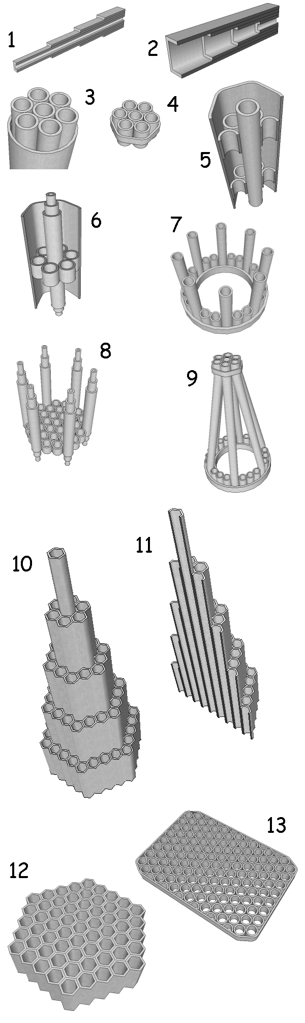
So, in the accompanying image, figure 1 shows how they di the Spitfire.
Very clever, not only does the strength distribution match the eliptical lift, it also follows the proportional thickness as well.
We can still use this in a classic "Hershey bar" wing too.
As seen in figure 2, reversing the lengths of the concentric spar tubes maintains external thickness while still distributing the the strength along the wing exactly where you need it.
Moving along to figure 3, we have what could be a tail boom tube reinforced against buckling by cramming a bundle of seven smaller tubes inside. The external tube should really be thinner-walled here as it's mostly there to tension the bundle together, but you get the idea.
If crammed tightly in there, the outer tube could distort if it's thin-walled, so we use a round-cornered hexagonal tube if we can. See figure 4.
If you shoved a hexagonal block of wood down the length of a thin-walled round tube could you make it a round-corner hexagon? Maybe, depending on the grade of aluminum.
Prior to cramming, I'd leave the outer tube in a sunny spot and the innder ones in the shade so the temperature expansion/contraction gives up that extra thousanth of and inch of clearance before the temps eaqualize and they tighten up.
Moving on to figure 5, we get a little fancy. we have a half-cutaway of a hex tube showing short sections of bundled tubes being used as little bulkheads along the length, with the center tube of the bundle extending the full length of the external tube. Why? Maybe it's a guide for a control cable, maybe its just reinforcement that's a little lighter than having the full bundle go all the way.
With figure 6, we start combining ideas. It's like number five, but the telescoped concentric tubes from 1 and 2 are added to the center tube. We can get some of that idealized stength distribution along a lever arm going on there.
In figure 7, large-diameter ring is reinforced with a ring of smaller tubes held in place by a second big ring.
This is a pretty strong geometry. The inner ring should be a bit thicker than the outer, as it's under pure compression. Probably should be spot-welded together so the little tubes don't pop out. Several of the little tubes are extended to act as stringers.
In figure 8, I went a little nuts, adding the concentric telescoping tubes to the stringer tubes. Not shown is the outer large ring that would hold it all together. In this case it would be a round-cornered hexagon.
Also, rather than an inner ring as in figure 7, it uses a bundle of small tubes.
Figure 9 is just figure 7 connected to figure 4 to form a nice tapered structure.
Figure 10 heads in a different direction. Thin-walled hex tubes of varying lengths are bundles together to form a tapering structure. I imagine this would have to be spot-welded tigether as you go, and use very thin-walled stuff.
Figure 11 is a cutaway of figure 10.
figure 12 are sections of hex tube used to create a bulkhead of sorts.
figure 13 does the same with round tubes used to create a rectangular one. Some of the tube sections needed to be cut in half legthwise for this. A band of aluminum wraps around the whole thing.
Both 12 and 13 would likely need to be spot-welded to a flat backing piece.
So that's it for now.
Just cutting and sticking various sizes and thickness of aluminum tube into each other can let you create a lot of specialized bits without expensive machining. The tubing in the images is being shown as much thicker-walled than it should be in order to see it clearly.
Let us begin our cram session.
(I am way too proud of that pun. Something horribly wrong with my brain.)
So, in the accompanying image, figure 1 shows how they di the Spitfire.
Very clever, not only does the strength distribution match the eliptical lift, it also follows the proportional thickness as well.
We can still use this in a classic "Hershey bar" wing too.
As seen in figure 2, reversing the lengths of the concentric spar tubes maintains external thickness while still distributing the the strength along the wing exactly where you need it.
Moving along to figure 3, we have what could be a tail boom tube reinforced against buckling by cramming a bundle of seven smaller tubes inside. The external tube should really be thinner-walled here as it's mostly there to tension the bundle together, but you get the idea.
If crammed tightly in there, the outer tube could distort if it's thin-walled, so we use a round-cornered hexagonal tube if we can. See figure 4.
If you shoved a hexagonal block of wood down the length of a thin-walled round tube could you make it a round-corner hexagon? Maybe, depending on the grade of aluminum.
Prior to cramming, I'd leave the outer tube in a sunny spot and the innder ones in the shade so the temperature expansion/contraction gives up that extra thousanth of and inch of clearance before the temps eaqualize and they tighten up.
Moving on to figure 5, we get a little fancy. we have a half-cutaway of a hex tube showing short sections of bundled tubes being used as little bulkheads along the length, with the center tube of the bundle extending the full length of the external tube. Why? Maybe it's a guide for a control cable, maybe its just reinforcement that's a little lighter than having the full bundle go all the way.
With figure 6, we start combining ideas. It's like number five, but the telescoped concentric tubes from 1 and 2 are added to the center tube. We can get some of that idealized stength distribution along a lever arm going on there.
In figure 7, large-diameter ring is reinforced with a ring of smaller tubes held in place by a second big ring.
This is a pretty strong geometry. The inner ring should be a bit thicker than the outer, as it's under pure compression. Probably should be spot-welded together so the little tubes don't pop out. Several of the little tubes are extended to act as stringers.
In figure 8, I went a little nuts, adding the concentric telescoping tubes to the stringer tubes. Not shown is the outer large ring that would hold it all together. In this case it would be a round-cornered hexagon.
Also, rather than an inner ring as in figure 7, it uses a bundle of small tubes.
Figure 9 is just figure 7 connected to figure 4 to form a nice tapered structure.
Figure 10 heads in a different direction. Thin-walled hex tubes of varying lengths are bundles together to form a tapering structure. I imagine this would have to be spot-welded tigether as you go, and use very thin-walled stuff.
Figure 11 is a cutaway of figure 10.
figure 12 are sections of hex tube used to create a bulkhead of sorts.
figure 13 does the same with round tubes used to create a rectangular one. Some of the tube sections needed to be cut in half legthwise for this. A band of aluminum wraps around the whole thing.
Both 12 and 13 would likely need to be spot-welded to a flat backing piece.
So that's it for now.