• Welcome aboard HomebuiltAirplanes.com, your destination for connecting with a thriving community of more than 10,000 active members, all passionate about home-built aviation. Dive into our comprehensive repository of knowledge, exchange technical insights, arrange get-togethers, and trade aircrafts/parts with like-minded enthusiasts. Unearth a wide-ranging collection of general and kit plane aviation subjects, enriched with engaging imagery, in-depth technical manuals, and rare archives.

    For a nominal fee of $99.99/year or $12.99/month, you can immerse yourself in this dynamic community and unparalleled treasure-trove of aviation knowledge.

    Embark on your journey now!

    Click Here to Become a Premium Member and Experience Homebuilt Airplanes to the Fullest!

Cowl Progress (or lack thereof)

This site may earn a commission from merchant affiliate links, including eBay, Amazon, and others.

Schmleff

Well-Known Member
Joined
Jan 2, 2006
Messages
2,714
Location
Waupaca, WI / USA
Well, as I started to try and work the cooling inlets in the way I wanted but I did indeed find an error in the way I laid the splines out. So.... I ripped it apart and started over again.

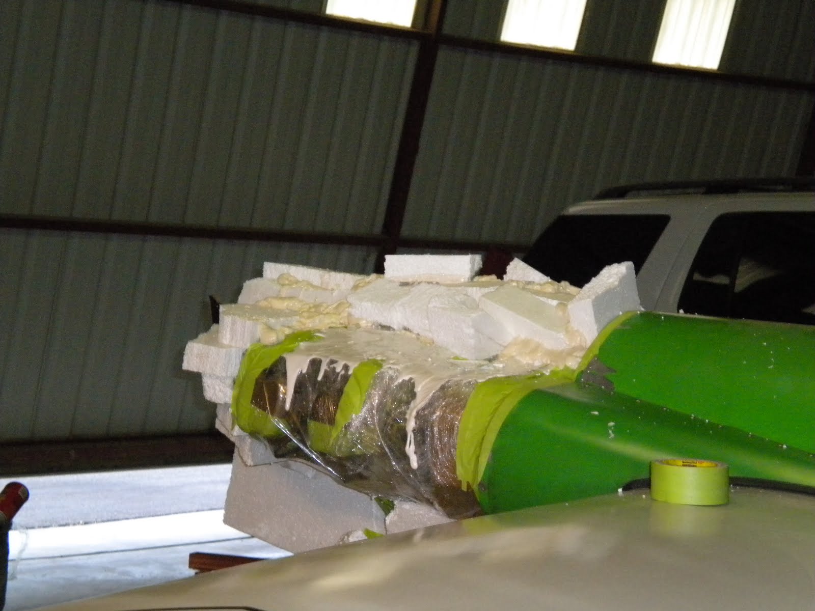
The cowl is only going to be on the aircraft for a year or two before I make a new one but I wanted to learn how to do it. The process is very fast and will save a lot of time on future projects. The entire plug was made in about 4 hours total. Many times faster and more accurate than doing it like the picture below :)

DSCN0278.JPG


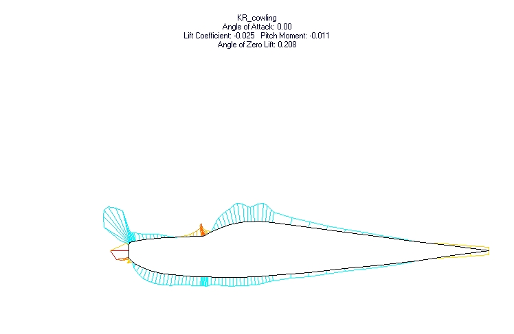
The nose of an aircraft with cheeks has got to be the most complex shape on the whole airplane. The rest of the cowl would be cake compared it. To give a brief summary, the main screw up was trying to extend the split line to accommodate the cooling inlets. Also, an object (like a cowl) needs to be treated as individual shapes with their own reference lines. The reference lines get splined first and each individual shape is splined. Any transition between shapes needs to be splined last.

I should have it done this weekend and will do a write up when finished.
 
It must really discouraging when you find out that you have to rip it all apart after all the work put into. What aircraft are you working on in that picture?
 
Yes and no. I need to get this thing in the air but at the same time learning something new is worth it.

Its Wassabi, a F1 racer, not mine.
 
Careful that expanding foam stuff is dimensionally unstable when exposed to most resins in composite work. Over time the foam shrinks and wilts and your mold will go to crap. I know because it has happened to me a couple of times, you have to work fast and get the parts done before the tooling starts to shrink.

I have seen it happen anytime between a week to a month.
 
Indeed. I use two part urethane if I have to make a plug from expanding foam. If you right click on the picture and open it in another tab, you can remove everything but the main URL and see the rest of his Picts.

Pictures like that are why I started messing with splines ; )
 
Almost there...

I went with stacked urethane foam so I could figure out the spline process. Its the same shape that it would have been if I had placed the splines properly. Its taking forever, but I understand how to spine the next similar item I make.
 

Attachments

  • cowl take 3.jpg
    cowl take 3.jpg
    300.6 KB · Views: 68
Almost ready to glass. I stuck a couple of mock inlets to the cowl to get a visual. Not sure about the size or placement yet. I am hoping to keep them just below the split line but they may have to get move up. There is higher pressure below the centerline of the spinner, but I am not sure if I can make a properly diverging duct to the baffles. The exhaust pipes will not go through the inlets or baffles.

Shaping by hand is a huge pain. I fought with getting the cheeks the same for days until finally I took some pictures and applied a grid with Photoshop. The stock cowl is way out of whack! I had to blend them to make them look the same even though they are not symmetrical.

More details on my blog at http://schmleff.blogspot.com
 

Attachments

  • Cowl2 5-29-131.jpg
    Cowl2 5-29-131.jpg
    280.8 KB · Views: 85
  • Cowl3 5-29-137.jpg
    Cowl3 5-29-137.jpg
    65.2 KB · Views: 73
No sir. I only need one nose bowl.

Even if I did make a mold, the part would likely not fit on another Sonerai. The existing part of the cowl is neither symmetrical or equal in measurements. The left cheek is about 13mm wider than the right one and I have modified the lower part of the cowl to clear the exhaust.
 
Looking good Jeff. I read the whole how to on the wasabi airplane on instructables.com when he redid his cowl. Its alot of work, I wish that I knew some people around here to teach me how to do it.
 
Jeff
I kinda liked the first go at the cowl shape, well I like them both I was just wondering was it the fact that you thought that first shape would not allow the inlet to be in a high pressure area or the looks that you changed to a rounder front check? Also are your parting/center line lined up with the spinner C/l? Please a photo of your cowl from above Thanks for any comments
 
Yes, I moved the cooling inlets to below the split line. Also, I should not have extended the fron of the cowl past the back of the spinner too far. A simple error on my part. Otherwise it's the same shape, just shorter.
 

Attachments

  • image.jpg
    image.jpg
    155.7 KB · Views: 77
Making sporadic progress. Took a 10 day cruise in Alaska and the next SAA magazine goes to the printers next week (I do the layout and graphic art for it).

It does not look like much progress, but the Picts show the actual bowl attached, reinforced and rough sanded. I am going to modify the left front exhaust pipe to allow for the cooling inlet and then start on the cooling system next.

I am running low on time before the Airventure Cup race...
 

Attachments

  • image.jpg
    image.jpg
    298.5 KB · Views: 71
  • image.jpg
    image.jpg
    336.2 KB · Views: 75
Thanks! It would look totally different if I was building the whole cowl from scratch, but I had to try and make it blend with what was there.
 
Finally took the plunge and cut the inlets in.

I messed with numerous inlet shapes and locations. I wanted to keep them below the leading edge for a two main reasons.

I wanted the inlets to be located where the pressure was the highest. Take a look at this diagram of the pressure distribution on the front of an airplane:

cowling_flow.gif


After looking at the and reading what others had written, I still don't quite understand why most say that the pressure is higher below the centerline of the spinner. Seems to me that it has more to to with if its below or above the leading edge of the cheeks of the cowl. Mark Langford had someone look at his cowl while he was placing the inlets on his KR.

pressure0.jpg


This diagram seems to indicated that the centerline of the spinner is not so critical. What is obvious from both diagrams is that the area of highest pressure is lower than our typical Sonerai inlets are placed.

Secondly, I wanted to be able to have an airtight seal between the inlet and the diffuser. The shape of the SI cowl makes this nearly impossible. If the seals are in the proper locations and orientations you cannot get the cowl on and off. Placing the inlets in the bottom cowl allows for the inlet to be secured to the diffuser after it is in place.

Unfortunately, this forced me to redo the exhaust routing on the front left cylinder so that it would not be in the way of the diffuser. More on this when I get to work on the rest of the cooling system.

Time to get back to work on the next SAA magazine which features both Tim's Sonerai and Scott's Hatz project in the "What our Members are Building" section!
 

Attachments

  • photo 4.JPG
    photo 4.JPG
    387.3 KB · Views: 83
Hi Jeff,
2 cents from Germany: the cowling is very pretty, but on your exhaust you produce a big ball of gas and this gas is like a big brake. For speed, it is a must, that the exhaust gas mus flow to behind direction. You remember, the efficiency of our engine is about 30% ---> 100hp for drive, 200hp for heating and exhaust pressure... so take the exhaust direction to backwards.
with best regards
Juergen
 
I have it facing as aft as possible given the limited space I have to work with. Other influencing factors are that I want the exhaust to stay below the wing and I don't want it to burn the fabric :)
 
Thanks for the pressure diagrams, it makes it easier to see why those little "smiley" cowls are adequate.
Neville
 
Back
Top