


Once again, the subject aircraft is my Rocket and more specifically, the IO-540-D4A5 engine up front. This is the paralell valve engine and features the familiar "log style" downdraft sump. This particular configuration has a very small common plenum area, sharp approach angles for the individual cylinder runners, and unequal length.
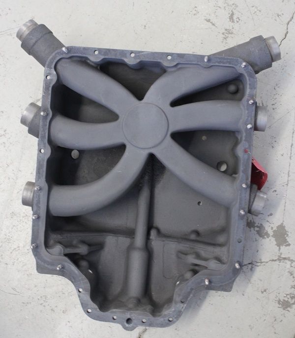
This configuration has worked OK for decades, but even the factory recognized the limitations. When they went with the better breathing angle valve head, they did a complete overhaul of the induction system. The so called "Tuned" induction features a large common plenum feeding individual induction trumpets, theoretically tuned for length. Appearance wise, it looks much more like a modern FI automobile than a 1948 Ford.

As part of a modification to the Rocket is to install one of these tuned sumps in an attempt to get the engine to breathe a bit better and increase the VE. It goes without saying that equal attention will be given to the exhaust, as they are very much complementary to overall VE. In the course of this modification I will be fabricating new induction tubes, which means I can make them any length I want. I can of course simply copy the Lycoming parts, but I don't know what their goal for VE was. I can also do the math and figure my typical RPM and DA to calculate the "optimim" runner length, but both of those solutions would still leave a hole in the data. They would show an improvement, or they wouldn't.
I'd like to do a real world, real time in situ test like I did when tuning Ross' CPI ignition recently. So with all that said, I have a plan and I'd like to throw it out for consideration. First off, I will calculate the theoretical optimum runner length based on my typical 2300RPM @ 8,500 cruise mission to see how close Lycoming got. For the in situ test however, my plan is to fabricate one tube that is variable in length over about 3 inches total. This will be controlled from the cockpit by a vernier knob/cable or functional equivelent.
So asuming I can make the hardware work on this single cylinder, what kind of behavior am I looking for? Well, unlike my pretty clear results on speed provided with the ignition tuning, I think it would take an unrealistic improvement on VE to see a single cylinder provide enough influence on total engine power to show up as a TAS change. Additionally, while I might theoretically find the resonant zone and improve this one cylinder dramatically, the overall air demand through the single servo feeding the common plenum is not going to increase much, so the mixture distribution is going to be off since all the injector nozzles are going to remain working on the common instructions from the servo - so again, TAS is unlikely to improve. So basically I'm creating an artificial "GAMI spread" through improved VE on one cylinder. So in theory I should be able to work the GAMI spread backwards and use it to find improvement, rather than problems. Without adding any airflow monitoring instrumentation, I think that I can watch EGT for the sweet spot. In the above scenario, an increase in VE on one cylinder out of 6 using a Bendix FI system should show that one cylinder go significantly lean, while the other 5 will go slightly rich as they respond to the servo, which sees a slight increase in airflow from the higher VE of the test cylinder.
So for the test scenario, I can set up cruise flight at altitude, RPM and 100 (or so) ROP EGT and start adjusting the length of the one runner. A VE improvement on that one cylinder should drive its mixture leaner, which will show up as an increase in EGT. In all actuality, the servo should respond to the slight contribution of this one cylinder to total airflow increase and will drive all 6 injectors slightly richer. So the 5 baseline cylinders should go slightly rich and drive EGT down, while the test cylinder will also see a slight mixture enrichment, but out of proportion to keep up with the increased VE, so will actually go lean, (hopefully significantly) driving EGT higher. Continuing this theory further, more adjustment of the test runner will bring it out of the resonant zone and VE will again drop back to toward parity with the other 5. I believe that adjustment through the full range will show a clear 'hump" in the EGT data, indicating optimum VE for that flight condition.
That's a lot to take in - But does anybody see a flaw in my logic, and if so, is there a better solution to finding true VE peaks short of an instrumented NASCAR dyno room?
This configuration has worked OK for decades, but even the factory recognized the limitations. When they went with the better breathing angle valve head, they did a complete overhaul of the induction system. The so called "Tuned" induction features a large common plenum feeding individual induction trumpets, theoretically tuned for length. Appearance wise, it looks much more like a modern FI automobile than a 1948 Ford.
As part of a modification to the Rocket is to install one of these tuned sumps in an attempt to get the engine to breathe a bit better and increase the VE. It goes without saying that equal attention will be given to the exhaust, as they are very much complementary to overall VE. In the course of this modification I will be fabricating new induction tubes, which means I can make them any length I want. I can of course simply copy the Lycoming parts, but I don't know what their goal for VE was. I can also do the math and figure my typical RPM and DA to calculate the "optimim" runner length, but both of those solutions would still leave a hole in the data. They would show an improvement, or they wouldn't.
I'd like to do a real world, real time in situ test like I did when tuning Ross' CPI ignition recently. So with all that said, I have a plan and I'd like to throw it out for consideration. First off, I will calculate the theoretical optimum runner length based on my typical 2300RPM @ 8,500 cruise mission to see how close Lycoming got. For the in situ test however, my plan is to fabricate one tube that is variable in length over about 3 inches total. This will be controlled from the cockpit by a vernier knob/cable or functional equivelent.
So asuming I can make the hardware work on this single cylinder, what kind of behavior am I looking for? Well, unlike my pretty clear results on speed provided with the ignition tuning, I think it would take an unrealistic improvement on VE to see a single cylinder provide enough influence on total engine power to show up as a TAS change. Additionally, while I might theoretically find the resonant zone and improve this one cylinder dramatically, the overall air demand through the single servo feeding the common plenum is not going to increase much, so the mixture distribution is going to be off since all the injector nozzles are going to remain working on the common instructions from the servo - so again, TAS is unlikely to improve. So basically I'm creating an artificial "GAMI spread" through improved VE on one cylinder. So in theory I should be able to work the GAMI spread backwards and use it to find improvement, rather than problems. Without adding any airflow monitoring instrumentation, I think that I can watch EGT for the sweet spot. In the above scenario, an increase in VE on one cylinder out of 6 using a Bendix FI system should show that one cylinder go significantly lean, while the other 5 will go slightly rich as they respond to the servo, which sees a slight increase in airflow from the higher VE of the test cylinder.
So for the test scenario, I can set up cruise flight at altitude, RPM and 100 (or so) ROP EGT and start adjusting the length of the one runner. A VE improvement on that one cylinder should drive its mixture leaner, which will show up as an increase in EGT. In all actuality, the servo should respond to the slight contribution of this one cylinder to total airflow increase and will drive all 6 injectors slightly richer. So the 5 baseline cylinders should go slightly rich and drive EGT down, while the test cylinder will also see a slight mixture enrichment, but out of proportion to keep up with the increased VE, so will actually go lean, (hopefully significantly) driving EGT higher. Continuing this theory further, more adjustment of the test runner will bring it out of the resonant zone and VE will again drop back to toward parity with the other 5. I believe that adjustment through the full range will show a clear 'hump" in the EGT data, indicating optimum VE for that flight condition.
That's a lot to take in - But does anybody see a flaw in my logic, and if so, is there a better solution to finding true VE peaks short of an instrumented NASCAR dyno room?
Last edited: